LED Display Technology: The Commercial Engineering Guide
Written and reviewed by the ETA Visual Engineering & Project Team. Guidance is updated when project, product or Singapore site-planning practices change.
Specifying an enterprise video wall based entirely on pixel pitch is one of the costliest engineering mistakes a project team can make. While procurement briefs often treat millimetre spacing as the primary metric, actual visual stability and operational lifespan depend on underlying LED display technology; specifically diode packaging physics, driver architecture, and thermal dissipation. If you've struggled to decode competing standards like SMD, GOB, and COB, or worried about premature module failure in Singapore's demanding humidity, you aren't alone. This guide cuts through vendor marketing to help you master the core engineering, packaging methods, and optical performance metrics behind modern commercial screens. You will gain a practical framework to evaluate contrast ratios, refresh rates, and viewing angles objectively, while formulating precise technical requirements for procurement and structural site preparation. Here is how modern diode assemblies function under the hood, and how to select hardware built for long-term commercial reliability.
Key Takeaways
- Understand the architectural fundamentals of commercial LED display technology, moving beyond raw pixel pitch to assess how true self-emissive diodes outperform legacy LCD matrices.
- Compare SMD, GOB, and COB packaging standards objectively to match physical impact protection, optical clarity, and moisture resistance to your installation environment.
- Look past headline brightness ratings by evaluating Pulse Width Modulation (PWM) driver performance, greyscale depth, and native contrast ratios.
- Mitigate thermal buildup and premature component degradation in humid tropical climates by specifying efficient common cathode circuit designs and proper cabinet ventilation.
- Utilise a systematic engineering framework to define viewing distances, ambient light thresholds, and structural mounting criteria before issuing procurement specifications.
Table of Contents
- Understanding Core LED Display Technology: From Diodes to Pixel Pitch
- Diode Packaging Standards Compared: SMD, GOB, and COB
- Critical Optical Performance Metrics: Refresh Rates, Greyscale, and Contrast
- Environmental Engineering and Structural Integration for Commercial Displays
- Specifying Commercial LED Displays: A Systems Integration Framework
Understanding Core LED Display Technology: From Diodes to Pixel Pitch
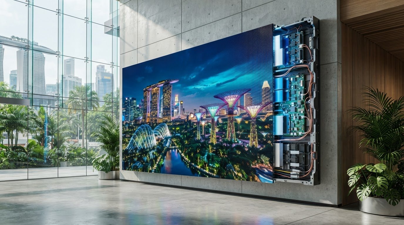
Direct-view commercial LED displays are engineered as modular matrices of microscopic, self-emissive semiconductor diodes. Unlike consumer screens, these systems do not rely on an external optical layer or global backlight. Instead, each individual pixel comprises discrete red, green, and blue (RGB) semiconductor chips mounted directly onto an integrated circuit board. As detailed in the foundational physics of LED display technology, passing an electrical current through these chips releases energy as photons, producing pure, controllable light at the individual diode level.
Commercial displays are built by assembling these diode matrices onto printed circuit boards (PCBs) to form compact modules. Multiple modules are then secured into precision die-cast aluminium cabinets. These modular cabinets tile edge to edge, daisy-chained via internal power supplies and data receiving cards to form a continuous, seamless digital canvas of virtually any custom aspect ratio or dimension.
The Mechanics of Self-Emissive Diode Architecture
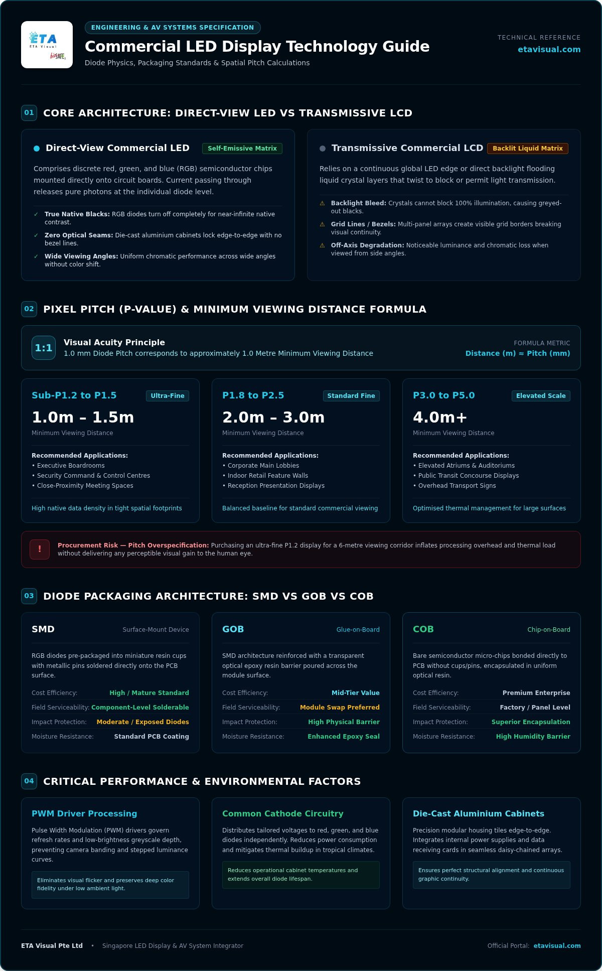
Self-emissive architecture provides immediate operational advantages over transmissive commercial LCD panels. In an LCD video wall, an edge or direct LED backlight continuously floods liquid crystal layers, which twist to block or pass light. Because liquid crystals cannot block 100% of illumination, LCDs suffer from light bleed, greyed-out black levels, and noticeable optical seams along panel borders.
Direct-view LEDs achieve native deep blacks simply by turning individual RGB diodes off completely. This per-pixel control yields near-infinite contrast ratios and uniform wide viewing angles without colour degradation. Cabinet-to-cabinet locking mechanisms also eradicate the bezel lines that disrupt multi-screen LCD arrays, ensuring uninterrupted graphic continuity across critical retail, transport, and control-room surfaces.
Calculating Pixel Pitch and Minimum Viewing Distance
Pixel pitch (denoted with a "P" prefix) measures the physical distance in millimetres from the centre of one pixel cluster to the centre of the adjacent one. A P1.5 display, for instance, features a 1.5 mm diode pitch. Pitch directly determines diode density, native cabinet resolution, and the minimum comfortable viewing distance for human eyes.
System designers generally apply visual acuity principles where 1 mm of pitch corresponds to approximately 1 metre of minimum viewing distance before individual diode points become discernible:
- Sub-P1.2 to P1.5: Recommended for close-proximity executive boardrooms and command centres viewing at 1 to 1.5 metres. For example, our enterprise deployment of fine-pitch indoor LED modules delivers uncompromised native data density in tight spatial footprints.
- P1.8 to P2.5: The balanced baseline for indoor retail feature walls and corporate lobbies viewed from 2 to 3 metres.
- P3.0 to P5.0: Practical for large elevated indoor spaces, overhead transport displays, and public concourses viewed from 4 metres or more.
A frequent procurement pitfall involves overspecifying ultra-fine pitch hardware for elevated or recessed installations. Purchasing a P1.2 screen for a 6-metre viewing corridor inflates processing overhead and thermal stress without delivering any perceivable visual gain to the viewer.
Diode Packaging Standards Compared: SMD, GOB, and COB
While pixel pitch dictates visual resolution, diode packaging defines the physical durability, thermal dissipation, and optical longevity of commercial LED display technology. Packaging refers to the mechanical method used to mount, bond, and seal semiconductor dies onto the PCB. In commercial procurement, matching the correct packaging standard to your site environment makes the difference between a resilient ten-year asset and an installation plagued by dead pixels and recurrent module repairs.
Surface-Mount Device (SMD) Packaging Architecture
Surface-Mount Device (SMD) packaging represents the mature workhorse of commercial digital video walls. In an SMD module, individual red, green, and blue diodes are pre-packaged into miniature rectangular resin cups with external metallic pins, which are soldered directly onto the printed circuit board via automated surface-mount placement.
SMD delivers strong cost efficiency and exceptional field serviceability; an AV technician can desolder and replace a single damaged pixel on-site using standard micro-soldering tools. However, SMD diodes remain mechanically exposed. Because the solder points sit on the PCB exterior, physical impacts from retail foot traffic, cleaning equipment, or luggage carts can dislodge diodes entirely. Additionally, exposed solder contacts remain vulnerable to ambient oxidation and moisture ingress in humid indoor environments.
Chip-on-Board (COB) and Glue-on-Board (GOB) Advancements
To overcome SMD's mechanical vulnerabilities, manufacturers developed Glue-on-Board (GOB) and Chip-on-Board (COB) architectures. GOB operates as a hybrid approach: standard SMD boards receive a transparent optical epoxy pour across the entire module face. This forms a flat, impact-resistant shield that repels moisture, dust, and physical contact, making it ideal for high-traffic public corridors and retail shopfronts.
COB represents a fundamental shift toward flip-chip micro-LED architecture. Instead of placing individual packaged diodes, bare microscopic semiconductor dies bond directly onto the circuit substrate before being encapsulated under a uniform resin coating. By eliminating lead wires and solder legs, COB achieves superior thermal dissipation directly through the board substrate. It also yields a seamless matte-black surface with expansive 170-degree viewing angles and exceptional contrast.
When engineering mission-critical environments or executive facilities, specifying fine-pitch indoor LED panels using COB packaging ensures sub-1mm diode structural integrity and optical uniformity. To evaluate how these packaging designs influence photometric output, engineers reference established optical performance metrics for LEDs to verify colour consistency across wide off-axis angles.
| Metric | Surface-Mount Device (SMD) | Glue-on-Board (GOB) | Chip-on-Board (COB) |
|---|---|---|---|
| Physical Protection | Low (Exposed diodes) | High (Hardened resin face) | Very High (Direct die encapsulation) |
| Moisture Ingress Resistance | Moderate (Vulnerable pins) | High (Front sealed) | Very High (Hermetic substrate seal) |
| Thermal Dissipation | Through solder pads | Through solder pads (insulating front) | Direct substrate conduction |
| On-Site Repairability | High (Single-pixel rework) | Low (Epoxy prevents local rework) | Requires factory module replacement |
| Typical Pitch Range | P1.5 to P10+ | P1.2 to P2.5 | P0.4 to P1.5 |
If you need help selecting between robust epoxy coatings and micro-pitch flip-chip substrates for an upcoming fit-out, speak with an LED specialist at ETA Visual to evaluate your facility's physical contact risks and environmental profiles.
Critical Optical Performance Metrics: Refresh Rates, Greyscale, and Contrast
Specifying a commercial video wall purely by peak nit brightness overlooks the variables that determine actual image quality. In real-world environments, raw luminance means very little if a screen crushes low-light details, displays harsh colour banding, or flickers violently through a camera lens. True optical performance in LED display technology relies on the interaction between driver integrated circuits (ICs), Pulse Width Modulation (PWM) switching frequencies, and panel contrast engineering.
Driver IC Architecture and Refresh Frequency Engineering
There is a fundamental difference between source frame rate and panel refresh frequency. While video content typically feeds into a system controller at 60Hz or 120Hz, the driver IC cycles current across individual diodes thousands of times per second. Entry-tier commercial displays often run at a baseline 1,920Hz refresh rate. While acceptable for static human viewing, 1,920Hz produces prominent black scan lines and rolling bars when captured by modern high-shutter smartphone cameras or commercial broadcast gear.
Professional installations require high-performance PWM driver ICs operating at 3,840Hz or up to 7,680Hz. These advanced ICs slice current pulses into narrower, high-frequency intervals without cutting the overall current load. This high-frequency switching prevents visual artefacts on camera feeds and stops the display from sacrificing greyscale precision during fast-motion media playback.
Contrast Ratios and Low-Brightness Colour Precision
High ambient contrast relies heavily on physical module surfaces rather than diode output alone. Manufacturers achieve deep native contrast by pairing matte black solder masks with non-reflective optical shaders. In fine-pitch environments, micro-louvre masks and anti-reflective surface coatings scatter ambient ceiling illumination. This ensures black levels remain perceptually true instead of washing out into dull charcoal grey.
The most demanding engineering challenge occurs when dimming indoor screens. Standard office lighting requires running indoor displays at only 20% to 30% of their maximum brightness. Cheap driver architectures suffer severe bit-depth compression when dimmed, causing 16-bit colour depths to drop to 8-bit or lower. The result is ugly colour contouring across shadow details.
To avoid this, enterprise-grade systems employ high-bit greyscale processing across the full dimming curve:
- 14-bit Greyscale: Provides 16,384 distinct shades per colour channel, suitable for basic digital signage and text-based corporate presentations.
- 16-bit Greyscale: Delivers 65,536 shades per channel, maintaining smooth gradients across deep shadows even at low brightness settings.
- HDR Calibration: Accurate tone-mapping for HDR10 and HLG standards, ensuring critical brand colours stay uniform in both high-bright accents and muted backgrounds.
For mission-critical monitoring, command centres, or broadcast studios, specifying dedicated control room AV solutions with native 16-bit greyscale processing ensures diagnostic imagery and complex surveillance feeds never lose tonal fidelity.
Environmental Engineering and Structural Integration for Commercial Displays
Deploying large-format LED display technology across commercial real estate demands meticulous structural and environmental planning. While factory spec sheets assume controlled test environments, commercial reality involves confined wall recesses, high ambient heat, and relative humidity often exceeding 80%. Without deliberate thermal pathways and structural load verification, premature diode degradation and power supply failures become inevitable.
Thermal Management and Power Efficiency in Tropical Climates
Sustained ambient heat accelerates semiconductor lumen depreciation and triggers uncalibrated colour shift. When internal cabinet junction temperatures rise unchecked, red, green, and blue diodes age at uneven rates, leaving visible chromatic blotches across the screen face.
Traditional common anode architecture supplies a uniform 5V power rail to all three diode colours. Because red semiconductor dies require only about 2.1V to operate while blue and green require roughly 3.2V, the excess 2.9V on the red channel converts directly into waste heat inside the cabinet. Specifying common cathode architecture resolves this inefficiency. Common cathode distributes split voltage rails (typically 2.8V to red and 3.8V to green and blue), slashing module thermal generation by up to 30% and significantly reducing the load on retail and office HVAC systems.
For flush recessed walls, passive rear convection slots or dedicated ducted plenum air extraction are mandatory to stop trapped heat pockets from baking internal receiving cards.
Structural Rigidity and Front-Maintenance Accessibility
Large modular displays exert continuous static and shear loads. Standard commercial drywall cannot safely bear large-format video walls without structural backing. Systems require engineered steel uni-strut frameworks or boxed RHS subframes anchored into reinforced concrete or structural brickwork to prevent cabinet sagging and panel misalignments.
Maintenance access dictates long-term operating costs. Rear-service installations require dedicated access corridors behind the screen, consuming valuable retail floor space. Enterprise indoor designs therefore rely almost exclusively on front-service engineering:
- Magnetic Vacuum Extraction: Electro-magnetic service tools attach directly to the front face of individual modules, releasing internal retention magnets for clean, non-destructive panel extraction in seconds.
- Electrical System Design: In compliance with Singapore Standard SS 638: 2018 for low-voltage electrical installations, high-resolution screens require dedicated three-phase distribution boards. Display power supplies cause substantial capacitive inrush currents upon startup; sequential turn-on relays and isolated earthing prevent false breaker trips.
- Preventive Maintenance: Regular thermal imaging, dust extraction, and contact inspections under preventive maintenance contracts protect capital assets against tropical humidity corrosion.
Specifying Commercial LED Displays: A Systems Integration Framework
Successful LED procurement requires translating architectural constraints and visual goals into a structured engineering specification. Evaluating LED display technology across five sequential integration stages ensures your capital expenditure delivers sustained operational performance:
- Viewing Geometry and Illuminance: Quantify exact audience sightlines, minimum viewing distances, and peak ambient lux levels across morning and afternoon daylight exposure.
- Packaging Selection: Match SMD, GOB, or COB packaging directly against physical contact risks, public traffic density, and ambient humidity conditions.
- Signal Pipeline Architecture: Map native canvas resolutions, redundancy paths, and optical distribution lines from central rack rooms to display cabinets.
- Site Infrastructure Audit: Verify structural subframe load capacities, dedicated breaker allocations, inrush limiters, and heat extraction airflow.
- Lifecycle Maintenance Protocols: Secure batch-matched spare modules and structured service level agreements for ongoing preventative servicing.
Signal Flow, Video Processing, and Media Management
A video wall is only as capable as its underlying processing chain. Master sending controllers ingest uncompressed video feeds, segment pixel data, and transmit synchronous packets to internal receiving cards across every cabinet. For corporate lobbies and executive briefing centres, specialised video processors handle low-latency multi-windowing, aspect-ratio scaling, and picture-in-picture switching between live video conferencing and dynamic signage feeds.
When system controllers sit in dedicated AV server racks dozens of metres away from the screen, copper HDMI or DisplayPort cables suffer signal degradation and electromagnetic interference. Integrating dedicated fibre-optic transceivers guarantees uncompressed, zero-latency 4K and 8K signal delivery over extended commercial pathways.
Working with a Professional AV System Integrator
Procuring raw display cabinets from an offshore catalogue does not equal an enterprise display system. Hardware reselling cannot substitute for experienced solution design, structural engineering calculations, LEW electrical coordination, and precision optical calibration. Without on-site calibration using high-precision colorimeters, adjacent cabinets from mismatched production bins exhibit noticeable seam lines and colour shifts.
Critically, reputable system integrators warehouse a dedicated reserve of batch-matched spare modules manufactured from the exact same diode silicon batch. Because LED diodes undergo subtle shifts in chromaticity and lumen output over years of continuous operation, replacing a failed module with unbinned factory spares creates visible patchwork discolouration across your screen.
Engaging our team for end-to-end commercial LED display integration ensures your digital assets are engineered for maximum uptime and visual impact. Contact our engineering team today to schedule a comprehensive site survey with ETA Visual for your upcoming commercial installation.
Building Long-Term Commercial Display Reliability
Selecting the right LED display technology isn't simply a matter of matching pitch numbers on a spreadsheet. Long-term visual stability and return on investment depend on pairing the correct packaging architecture with disciplined thermal engineering, robust PWM driver control, and uncompromised structural integration.
ETA Visual brings a proven engineering track record delivering complex AV installations across corporate headquarters, premier retail venues, and public transport infrastructure. We take full accountability for your project lifecycle, managing everything from structural calculations and low-voltage electrical coordination to sub-pixel optical calibration. Backed by dedicated preventive maintenance agreements and local rapid-response troubleshooting teams, we ensure your visual infrastructure operates at peak performance throughout its working life.
With an experienced systems integrator managing your deployment, your digital canvas will deliver uncompromised clarity, uniform colour accuracy, and reliable uptime from day one.
What is the fundamental difference between an LCD video wall and an LED display?
Commercial LED displays are direct-view and self-emissive, whereas LCD video walls rely on edge or rear backlights shining through liquid crystal panels. Because each LED pixel illuminates independently, direct-view displays eliminate grid bezels entirely and achieve true zero-luminance blacks. LCD walls inevitably display visible seam lines between panels and suffer from light bleed across dark backgrounds.
What does pixel pitch mean, and how does it determine image sharpness?
Pixel pitch is the physical centre-to-centre distance between adjacent diode clusters measured in millimetres. It directly sets pixel density and display resolution. A smaller pitch, like P1.2, packs more diodes into a square metre than a P2.5 screen, delivering sharper close-range detail. For commercial displays, human visual acuity typically requires roughly one metre of viewing distance for every millimetre of pixel pitch to perceive a continuous image.
Is COB packaging genuinely better than standard SMD technology for indoor screens?
Chip-on-Board (COB) is significantly better for fine-pitch indoor installations below P1.5 and high-traffic corridors, but SMD remains practical for standard displays. COB bonds bare dies directly to the board beneath a protective resin coat, creating high impact resistance and superior heat dissipation. However, standard SMD provides easier single-pixel field repairability at a lower manufacturing baseline for larger viewing distances.
Why do commercial LED displays look clear to the eye but flicker on smartphone cameras?
Camera flicker occurs when the display driver's diode switching frequency conflicts with the camera shutter speed. Human eyes integrate light smoothly, but digital sensors capture high-speed switching intervals. Screens running at a baseline 1,920Hz often exhibit rolling dark scan lines on phone cameras. Specifying advanced PWM driver ICs with refresh rates of 3,840Hz or higher resolves this timing conflict, keeping screens crisp in photos and live broadcast feeds.
How long do commercial LED displays last before experiencing significant brightness loss?
Commercial screens typically operate for roughly 100,000 hours before reaching half-brightness (L50), depending on thermal conditions and operating load. In warm tropical climates, running displays continuously at maximum brightness accelerates diode degradation and chromatic drift. Modern LED display technology running on energy-efficient common cathode power designs operates much cooler, typically retaining stable colour calibration and high luminance beyond seven to ten years of commercial indoor service.
What electrical and cooling infrastructure is required for large indoor LED video walls?
Large video walls require dedicated three-phase electrical distribution boards designed to handle capacitive inrush currents upon startup, compliant with Singapore Standard SS 638. Installations should incorporate sequential turn-on relays and isolated earthing. For flush recessed walls, adequate passive convection slots or ducted plenum extraction must maintain continuous airflow behind the cabinets to prevent trapped heat from degrading internal power supplies and receiving cards.
Can individual damaged pixels or modules be repaired on-site without replacing the entire screen?
Yes, commercial systems are modular, meaning you never need to replace an entire screen. Technicians extract individual magnetic modules from the front face within seconds. With traditional SMD modules, technicians can micro-solder single replacement diodes on-site. For COB or GOB modules, the affected panel is swapped instantly with a batch-matched spare from your reserved inventory, while the damaged unit undergoes specialised workshop repair.
Visual planning reference
| Metric | Surface-Mount Device (SMD) | Glue-on-Board (GOB) | Chip-on-Board (COB) |
|---|---|---|---|
| Physical Protection | Low (Exposed diodes) | High (Hardened resin face) | Very High (Direct die encapsulation) |
| Moisture Ingress Resistance | Moderate (Vulnerable pins) | High (Front sealed) | Very High (Hermetic substrate seal) |
| Thermal Dissipation | Through solder pads | Through solder pads (insulating front) | Direct substrate conduction |
| On-Site Repairability | High (Single-pixel rework) | Low (Epoxy prevents local rework) | Requires factory module replacement |
| Typical Pitch Range | P1.5 to P10+ | P1.2 to P2.5 | P0.4 to P1.5 |
Want an accurate budget for your space?
We'll do a free site survey and prepare a clear, itemised quotation — no obligation.
Frequently asked questions
Commercial LED displays are direct-view and self-emissive, whereas LCD video walls rely on edge or rear backlights shining through liquid crystal panels. Because each LED pixel illuminates independently, direct-view displays eliminate grid bezels entirely and achieve true zero-luminance blacks. LCD walls inevitably display visible seam lines between panels and suffer from light bleed across dark backgrounds.
Pixel pitch is the physical centre-to-centre distance between adjacent diode clusters measured in millimetres. It directly sets pixel density and display resolution. A smaller pitch, like P1.2, packs more diodes into a square metre than a P2.5 screen, delivering sharper close-range detail. For commercial displays, human visual acuity typically requires roughly one metre of viewing distance for every millimetre of pixel pitch to perceive a continuous image.
Chip-on-Board (COB) is significantly better for fine-pitch indoor installations below P1.5 and high-traffic corridors, but SMD remains practical for standard displays. COB bonds bare dies directly to the board beneath a protective resin coat, creating high impact resistance and superior heat dissipation. However, standard SMD provides easier single-pixel field repairability at a lower manufacturing baseline for larger viewing distances.
Camera flicker occurs when the display driver's diode switching frequency conflicts with the camera shutter speed. Human eyes integrate light smoothly, but digital sensors capture high-speed switching intervals. Screens running at a baseline 1,920Hz often exhibit rolling dark scan lines on phone cameras. Specifying advanced PWM driver ICs with refresh rates of 3,840Hz or higher resolves this timing conflict, keeping screens crisp in photos and live broadcast feeds.
Commercial screens typically operate for roughly 100,000 hours before reaching half-brightness (L50), depending on thermal conditions and operating load. In warm tropical climates, running displays continuously at maximum brightness accelerates diode degradation and chromatic drift. Modern LED display technology running on energy-efficient common cathode power designs operates much cooler, typically retaining stable colour calibration and high luminance beyond seven to ten years of commercial indoor service.
Large video walls require dedicated three-phase electrical distribution boards designed to handle capacitive inrush currents upon startup, compliant with Singapore Standard SS 638. Installations should incorporate sequential turn-on relays and isolated earthing. For flush recessed walls, adequate passive convection slots or ducted plenum extraction must maintain continuous airflow behind the cabinets to prevent trapped heat from degrading internal power supplies and receiving cards.
Plan the next step
Continue with a relevant solution and real Singapore project evidence.